
Text, figures: Leandro Madrazo, October 1994
Objectives.
This exercise will focus on the construction of three-dimensional objects over a two-dimensional plane. The basic concepts to operate with a three-dimensional computer modeling program will be introduced. Some of the ideas that were presented in the first exercise, like types and instances, design alphabet and theme and variations, will be further expanded in this exercise.
Types and Instances.
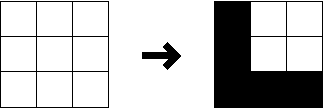
In this exercise you will build your own design alphabet, rather than using the one that is given to you. In the TYPES+INSTANCES program the simplest shapes of the alphabet are called PROFILES. Following with the language analogy, a PROFILE is the equivalent to the letter in the alphabet of a language. In the T+I program, a PROFILE is a shape that results from joining the cells on a 3x3 grid (Figure 2.1).

Fig. 2.1. The interface to create extruded profiles.
To make a PROFILE you use the command CREATE PROFILE. After you invoke the command you get the 3x3 grid. By selecting some of the individual cells of the grid on the screen and by create a profile on the grid, like and 'L' shape, a 'U' shape or any othe possible combination. A variety of shapes can be created in this way (Figure 2.2). Each shape or PROFILE is assigned a color when is created. This means that you can have in your design alphabet a PROFILE that is a RED "L" and another one that is a BLUE "L", for example. The collection of profiles that you created represents your design alphabet.

Fig. 2.2. A typical design alphabet made up of PROFILES.
There are, however, some restrictions to the PROFILES that can be created: the shapes have to touch the four sides of the outer square, they have to define only one shape, and the shape with a whole in the middle cannot be created. Figure 2.3 shows some 'illegal' shapes that are not accepted by the TYPES+INSTANCES program.

Fig. 2.3. Some 'illegal' PROFILES.
Even though the shapes that you create in the 3x3 grid are two-dimensional profiles, they are in fact three-dimensional. After you select a shape, the program automatically applies an extrusion to the shape to transform it into a three-dimensional shape which. Therefore, the PROFILES are three-dimensional and they are contained within a imaginary cube or 1 unit side, called 'bounding box'.
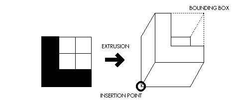
Fig. 2.4. Extrusion of the shape and bounding box.
To create your objects, you can proceed to instantiate the PROFILES in the drawing using the command INSTANTIATE PROFILE, as in the first exercise. This time, however, your 'instances' will be three-dimensional. This means that when you insert an instance of a PROFILE you will give a certain value for the height of the object. Figure 2.5 shows the paradigm TYPES and INSTANCES adapted for the new situation with three-dimensional objects.
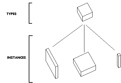
Fig. 2.5. The paradigm TYPES and INSTANCES applied to three-dimensional objects.
After you have inserted those instances in your drawing, you can later change their dimensions and location with different editing commands. You can use, for example, the AutoCAD commands MOVE, SCALE, ROTATE and MIRROR that you already know from last exercise. Also, you can use specific commands from the T+I program, like RESIZE, SPIN, FLIP and CHANGE PARAMETER for similar purposes. RESIZE and CHANGE PARAMETER are particularly useful to change the dimensions of the instance.
You can also make 'global changes' to your instances by redefining the PROFILE itself. This is a particularly interesting consequence of the TYPES and INSTANCES paradigm. Since the instances are linked to the type, any changes in a type will propagate to all of its instances. Thus, for example, if you want to change all the instances that are red to blue, you can invoke the command EDIT PROFILE and change the color of the profile from red to blue. When you return to the drawing, all the instances that were previously red will be changed into blue. You can proceed in a similar way to transform a L shape into a U shape or any other.
The instances of a PROFILE can adopt a variety of proportions, depending of the values you give to their parameters. They can be more like planes, or more like boxes or columns. In each case, there are a different set of spatial relationships to be considered. Figure 2.6 shows some spatial relationships of a set of parallel planes and a set of boxes.
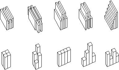
Fig. 2.6. Spatial relationships of plane-plane and box-box.
Description of the exercise.
In the drawing prepared for this exercise, you will find a grid of 12 squares. As in the first exercise, every row corresponds to a theme and its subsequent variations. This time, the themes are the following:
- Theme 1. Extruded Forms. Composition of objects placed on the cells of a two-dimensional grid. (see examples from past Semesters)
- Theme 2. Parallel Planes. Composition of planar objects placed on a two-dimensional surface. (see examples from past Semesters)
- Theme 3. Substitution. Variations created as a result of replacing objects of a given composition by other objects of the design alphabet. (Figure 2.7)

Fig. 2.7. Example of variations created by means of substitution.
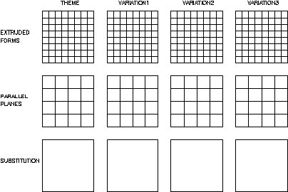
Fig. 2.8. Exercise layout: themes and variations for objects on a plane.